
EQUINOX Configurator
EQUINOX Configurator is the system’s configuration utility.
It allows the developer to define all the configuration parameters required. It was designed to give the user complete freedom to make any kind of change without having to rely on the vendor.
Special emphasis was also placed on making the tool intuitive and easy to understand, so that it can be used by people with limited knowledge of HMI/SCADA systems.
To use this module make sure EQUINOX Core is running, otherwise the database will not be available.
Module operation
To access EQUINOX Configurator, run its shortcut located in the start menu or on the desktop.
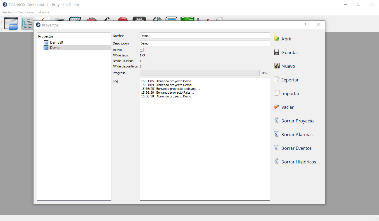
The first window shown is the project selection window:
| Action | Description |
|---|---|
| Open | Opens the selected project |
| Export | Exports the selected project, generating a file with the .eqpro extension in the “export” subfolder within the program folder |
| Import | Use this button to select an .eqpro file and import it into this project’s structure. WARNING: This will erase the currently saved contents. To avoid this, create a new project first |
| New | Creates a new (empty) project |
| Clear | Empties the contents of the selected project |
| Delete | Deletes the selected project |
| Name | Assigns a name to the project |
| Description | Assigns a description to the project |
| Active | Determines whether the project will be loaded when the system starts. Only one project can be active at a time; selecting one automatically deselects the previous one. There must always be an active project |
Element Tree section
This section allows the creation of the system’s Element Tree, that is, the definition of the data acquisition elements: Stations, Devices, Communication Channels and Scan Groups, and their relationships with each other, to reflect the architecture of the network of elements connected to the SCADA system.
| Element | Description |
|---|---|
| Stations | Groups devices according to their nature or function |
| Devices | Concept that represents data acquisition and control elements. A hardware address and the telecontrol protocol to be used are defined. |
| Scan Groups | Blocks of data to be read from the devices periodically. The data type and subtype to be queried, the start and end index, and the polling period are defined. They can be reused, so if needed they are defined once and assigned to multiple devices. |
| Communication Channels | Communication links between the system and the devices. The port type (serial or TCP/IP) is defined, along with the channel timeout; for serial ports the port, speed and parity are defined, and for TCP/IP sockets the IP and port are defined. It can be assigned to multiple devices when they share the same communication channel (multidrop bus) |
| Relationships between elements | Operational relationships are established between Stations, Devices, Scan Groups and Communication Channels. For more information about this feature, see the following documentation. |
Other sections
| Section | Description |
|---|---|
| Points | Creation of information points that will later be represented on Displays |
| Displays | Definition of displays where certain points will be represented using graphical symbols |
| Text Sets | Lists of texts to assign to the different states a digital point can take (Example: 0 = Open, 1 = Closed) |
| Limit Sets | Limit values to later assign to analog points and generate alarms if they are exceeded |
| Functions | Definition of functions for converting raw counts to engineering units or for operations with calculated points |
| Alarm Groups | Groups that contain points with the same priority or criticality |
| Command Sets | Definition of telecommands |
| Sequential Complex Commands | Definition of lists of complex telecommands to be executed sequentially |
| Calculations | Assignment of parameters to Functions to determine the values of calculated points |
| Tasks | Definition of scheduled tasks |
| Users | Creation of users with system access permissions, and determination of permissions and areas of responsibility |