
Scan Group
A Scan Group defines a block of information that will be read from a Device at regular intervals. The same Scan Group can be shared by several Devices if the same information is to be acquired from them; in this case, even though it is the same Scan Group, each Device will handle the information read independently, with no interference between them.
Four concepts are defined:
| Concept | Description |
|---|---|
| Data type to be polled | The nature of the information to be obtained from the Device. Generically, these are input or output registers, either analog or digital. Registers may be, for example, 1 or 2 bits long for digital points and 16 or 32 bits long for analog points |
| Range | Devices internally store a certain number of registers of one or more types. Each of these registers has a sequence number that distinguishes it from the rest. When the system sends a poll, it specifies a starting and an ending sequence number. The Device must respond with all the registers whose sequence number falls within the specified interval. This interval is known as the polling range |
| Period | Determines the time the system will wait before sending a new request or poll of this type |
| Protocol | The telecontrol protocol with which the system will send the poll. This does not change the content or meaning of the message, only the language in which it is transmitted to the Device |
Screenshot
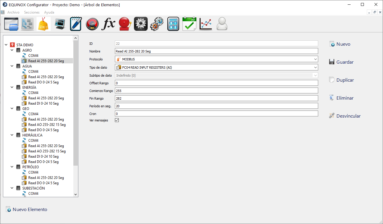
Definition
- Select another Scan Group from the list and click the New button in the upper right area of the window
- If no Scan Group has been defined yet, click New Element, select Scan Group from the list and click Ok
- Fill in the following fields
Field Description Name Name of the scan group Protocol MODBUS or DNP (check which protocols are enabled in your license) Data Type Select according to the protocol (see below) Data Subtype Select according to the protocol (see below) Offset Numeric value added as an offset to all points assigned to this Scan Group; enter 0 if not used Start Starting index, address or register (not counting the base address, example: for 40.010 enter 10) Stop Ending index, address or register (same as above) Period in sec Interval in seconds between sending this poll packet View messages Check if you want data exchanges related to this Scan Group to be shown in the Core module - Click Save
Data Type and Subtype definitions for the Modbus protocol
For Data Type you must select one of the following function codes; the Data Subtype field remains disabled since it does not apply to this protocol.
| Type | Description |
|---|---|
| FC01 Read Coil Status | Reading of digital outputs (Function Code 1) |
| FC02 Read Contact Status | Reading of digital inputs (Function Code 2) |
| FC03 Read Holding Registers | Reading of analog outputs (Function Code 3) |
| FC04 Read Input Registers | Reading of analog inputs (Function Code 4) |
Data Type and Subtype definitions for the DNP protocol
For Data Type you must select one of the following DNP objects, and based on this selection choose the Data Subtype
| Type | Subtype | Description |
|---|---|---|
| BINARY INPUT | SINGLE BIT, WITH STATUS | Reading of digital inputs |
| BINARY OUTPUT | SINGLE BIT, WITH STATUS | Reading of digital outputs |
| ANALOG INPUT | 16-BIT, 32-BIT, 16-BIT WITHOUT FLAG, 32-BIT WITHOUT FLAG | Reading of analog inputs |
| ANALOG OUTPUT | 16-BIT, 32-BIT | Reading of analog outputs |
| WRITE TIME AND DATE | — | Writing of the current SCADA date and time to the device. |
Other buttons
| Button | Description |
|---|---|
| Duplicate | Creates a new Scan Group with the same settings |
| Delete | Deletes the Scan Group |
| Unlink | Allows unlinking the Scan Group from the Device it is linked to |